In the previous Arduino LCD tutorial, you have noticed that the classic parallel LCD consumes a lot of pins on the Arduino. Even in the 4-bit mode, it requires at least 6 digital I/O pins on the Arduino. So in many projects where you use the classic parallel LCD, you will run out of pins very easily.
The solution to this problem is to use an I2C LCD display. It requires only two digital I/O pins and you can even share those two pins with other I2C devices.
In this tutorial, I will show you how to interface an I2C LCD with Arduino Uno and print some text, numbers, and custom characters.
Table of Contents
I2C LCD Overview
An I2C LCD display consists of a classic parallel LCD and an I2C LCD adapter. The I2C LCD adapter is soldered from the back of the LCD.
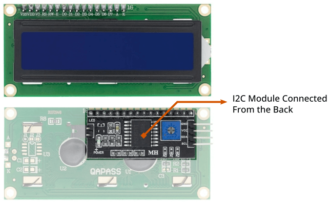
If you already have an LCD you can only purchase the I2C LCD adapter and solder it by yourself.
Now let’s have a look at the LCD display and the I2C LCD adapter in detail.
Liquid Crystal Display (LCD)
Commonly available LCD displays with I2C LCD adapters are 16×2 and 20×4 character LCD displays. They both have a total of 16 pins including 8 parallel data pins. So if you don’t use an I2C LCD you will need at least 6 digital I/O pins on the Arduino to display something.
If you look closely you will find that the characters of the LCD are built using a grid of 5×8 pixels. Later in this tutorial, you will learn how to turn on and off any individual pixels to make custom characters.
You can read more about the LCD display in my Arduino LCD tutorial.
I2C LCD Adapter Overview
At the center of this adapter, there is an 8-bit I/O expander chip – PCF8574. It takes the I2C data from the MCU (Arduino) and converts it into serial data required for an LCD display. On one side the I2C LCD adapter has four pins that can be connected to Arduino or any microcontroller that supports the I2C communication protocol. On another side, it has 16 pins that are connected to the LCD display.
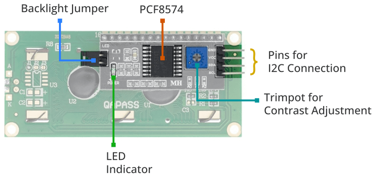
There are two header pins to control the backlight of the LCD display. One pin supplies a 5v power and another pin is for the backlight LED. These two pins are connected together by default. So the backlight will be always on. You can remove the jumper to turn off the backlight LED or you can use a potentiometer in between these two pins to control the intensity of the backlight LED.
The I2C LCD adapter also has a small trim pot to adjust the contrast of the display.
How to Change the Default I2C Address
Some I2C LCD adapters come with PCF8574, while others use PCF8574A chips. Each of these chips has its own I2C address. The PCF8574 chip from NXP Semiconductor uses 0x27 while the PCF8574A chip uses 0x3F.
Sometimes you need to change this default I2C address for a project where you use multiple I2C devices on the same I2C bus So that it does not conflict with other I2C devices.
If you use multiple I2C devices on the same I2C bus, sometimes you need to change this default I2C address to avoid conflict with other I2C devices.
To change the default address it has address selection pads – A0, A1, and A2.
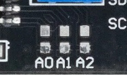
Each of these pads has a ground connection above it. By default, each of these pins is connected to VDD or a positive power supply. You can change the address by connecting any pin to the ground pin above it. You can make any possible combination and you will get a different address. From three address pins, you can get 23 different combinations means 8 different addresses.
If you go through the datasheet of PCF8574 by NXP, you will find that PCF8574 and PCF8574A use a 7-bit I2C address. The first four-bit is fixed and the last three-bit is hardware selectable.

As you read above A0, A2, and A3 are connected to the positive power supply by default. So the default address of PCF8574 is 0100111 in binary or 0x27 in hex. If you connect the A0 pin to the ground pin it will become logic LOW. The address will change to 0100110 in binary or 0x26 in hex.
See the illustration below to find all the possible connections and the hex addresses.

In the same way, you can change the address of a PCF8575A chip. But keep in mind that the first four bits of the PCF8575 are 0100 and the first four bits of the PCF8575A are 0111. Calculate the address according to it.
I2C LCD Pinout
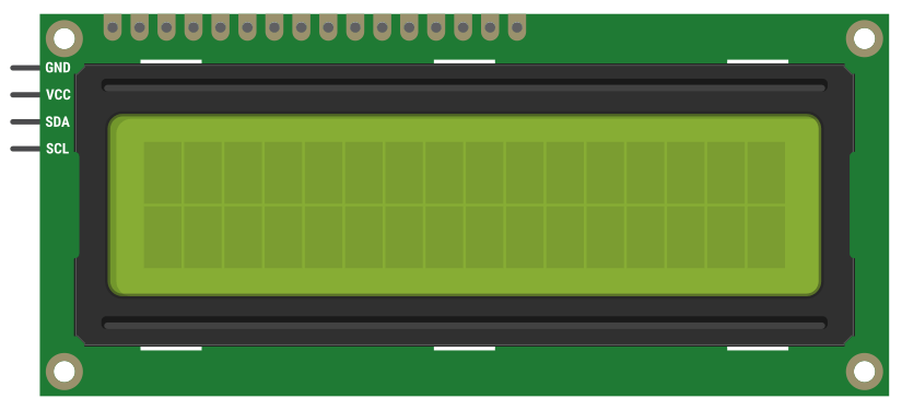
The I2C LCD display has four pins coming out from the I2C LCD adapter. These four pins are – Ground, VCC, SDA, and SCL.
You can see the pinout of an I2C LCD display in the image below.
Parts required for this Tutorial
| SL. | Preview | Name | Link |
|---|---|---|---|
| 1 |  | Arduino Uno R3 | Amazon | Aliexpress |
| 2 |  | I2C LCD | Amazon | Aliexpress |
| 3 |  | Jumper Wires | Amazon | Aliexpress |
Connect an I2C LCD with Arduino
Connecting an I2C LCD display with Arduino is very simple compared to a normal LCD display. You only need to connect four wires to the Arduino.
Connect the LCD’s VCC pin to the Arduino 5v pin and the Ground pin to the Arduino Ground pin. The remaining two pins are SCL and SDA. You need to connect the SCL pin to the Arduino SCL pin and SDA to the Arduino SDA pin.
On the Arduino Uno, the SCL pin is A5 and the SDA pin is A4 pin, connect it accordingly.
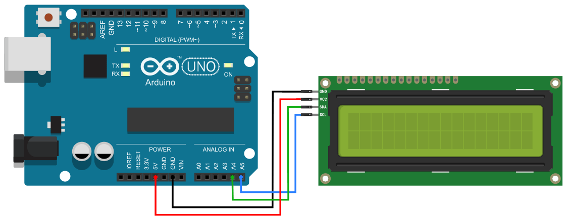
If you are using a different Arduino board, you will find the SCL and SDA pin for the respective board in the below table.
| Arduino Board | SCL Pin | SDA Pin |
|---|---|---|
| Arduino Uno | A5 | A4 |
| Arduino Nano | A5 | A4 |
| Arduino Micro | 3 | 2 |
| Arduino Leonardo | 3 | 2 |
| Arduino Mega 2560 | 21 | 20 |
| Arduino Due | 21 | 20 |
Arduino I2C LCD Code
In this tutorial, I am using the LiquidCrystal-I2C library to control the display. It has many pre-built functions to control an I2C LCD display in a much simpler way.
To install the library first you need to download it from the LiquidCrystal-I2C GitHub repository. Then open your Arduino IDE and navigate to Sketch > Include Library > Add .ZIP Library.
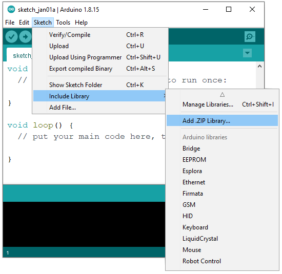
Select the .zip file you just downloaded and click the open button. The installation is done, now you can include the library in your code.
Find the I2C address of your LCD
You need to know the I2C address of the LCD before starting the communication. To know the I2C address of your LCD run the below sketch.
#include <Wire.h>

void setup() {
  Serial.begin(9600);

  Serial.println("\nI2C Scanner");
  Serial.println("Scanning...");
  byte device_count = 0;

  Wire.begin();
  for (byte address = 1; address < 127; address++ ) {
    Wire.beginTransmission(address);
    if (Wire.endTransmission() == 0) {
     // Serial.print ("Found address: ");
      Serial.print("I2C device found at address 0x");
      Serial.print(address, HEX);
      Serial.println("  !");
      device_count++;
      delay(1);
    }
  }
  Serial.println ("Done.");
  Serial.print ("Found ");
  Serial.print (device_count);
  Serial.println (" device(s).");
}

void loop() {}
Open the serial monitor on the Arduino IDE and you will get a result like this –
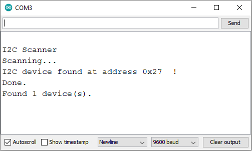
Note down the I2C address of your LCD somewhere. You will need it later in the following sketches.
Arduino I2C LCD – Print a Simple Text
Printing text on the LCD is very simple. The below sketch will print some text on the display. But before uploading this sketch you need to make some minor changes according to your display size and address.
In the second line, I created a LiquidCrystal_I2C variable. It requires three variables – the I2C address of the LCD and the dimension of the LCD (columns and rows of the display). The I2C address of my display is 0x27 and it has 16 columns and 2 rows. So I will use – LiquidCrystal_I2C lcd(0x27,16,2). If you have a different LCD display change the I2C address and dimension accordingly.
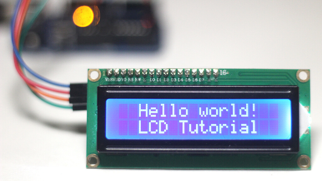
Now the sketch is ready for your display. Upload it to your Arduino board and see the output.
Code to Print a Simple Text
#include <LiquidCrystal_I2C.h>

LiquidCrystal_I2C lcd(0x27,16,2);

void setup() {
  lcd.init();
  lcd.clear();
  lcd.backlight();

  lcd.setCursor(2,0);
  lcd.print("Hello world!");

  lcd.setCursor(2,1);
  lcd.print("LCD Tutorial");
}

void loop() {}
Explaining the Code
The sketch is very simple. It begins with including the LiquidCrystal_I2C header file – #include LiquidCrystal_I2C.h>
Then you need to define a LiquidCrystal_I2C variable for your LCD. It requires three variables – the I2C address of the LCD and the dimension of the LCD (columns and rows of the display).
Then in the setup section, you have to initialize the display using the init() function. The clear() function will clear the display buffer. It is good to clear the display buffer before printing anything on the display so that it does not display anything that was previously stored in the display buffer.
backlight() – this will turn on the display backlight.
setCursor(col, row) – this will set the cursor to a position from where the text and characters will print. This function requires two variables – columns, and rows.
One thing to note here is that columns and rows counting start from the top left corner and it starts with (0, 0).
print() – this will print text and characters on the display.
Now you can understand that first I set the cursor to the third column of the first row and printed some text there.
lcd.setCursor(2,0);
lcd.print("Hello world!");
Then I set the cursor to the third column of the second row and print some text there.
lcd.setCursor(2,1);
lcd.print("LCD Tutorial");
For this example, we don’t have to use the loop section, so leave it blank.
Useful Functions from the Library
In this section, I have picked some useful functions from the library and discussed them. I have written some example code where needed. Try to run those codes and see the output. You will understand the function very easily.
clear() – Clears the display and places the cursor at the top left corner. You can use this function to display different text/strings at the same place at a time. The below code shows the use of this function.
#include <LiquidCrystal_I2C.h>

LiquidCrystal_I2C lcd(0x27, 16, 2);

void setup() {
  lcd.init();
  lcd.backlight();
}

void loop() {
  lcd.clear();
  lcd.print("Hello !");
  delay(1000);
  lcd.clear();
  lcd.print("Welcome to");
  delay(1000);
  lcd.clear();
  lcd.print("Circuit Geeks");
  delay(1000);
}
home() – Places the cursor at the top left corner of the display without clearing the display.
cursor() – Displays the LCD cursor. The default cursor is an underscore line.
noCursor() – Hides the LCD cursor.
blink() – Creates a blinking block-type LCD cursor.
noBlink() – Disable the blinking-block type LCD cursor.
display() – Turns on the LCD screen and displays the texts/characters that were previously printed on the display.
noDisplay() – Turns off the LCD screen but does not clear data from the LCD memory. The below code shows the use of display() and noDisplay() functions.
#include <LiquidCrystal_I2C.h>

LiquidCrystal_I2C lcd = LiquidCrystal_I2C(0x27, 16, 2);

void setup() {
  lcd.init();
  lcd.backlight();
  lcd.print("Blinking Display");
}

void loop() {
  lcd.display();
  delay(1000);
  lcd.noDisplay();
  delay(1000);
}
write() – This function is used to write a character to the display. You can see the use of this function in the I2C LCD custom character section below.
scrollDisplayLeft() – Moves the display content one step to the left. You can use this function in a loop to create a scrolling text effect.
scrollDisplayRight() – Moves the display content one step to the right. The below code shows the use of these functions.
#include <LiquidCrystal_I2C.h>

LiquidCrystal_I2C lcd = LiquidCrystal_I2C(0x27, 16, 2);

void setup() {
  lcd.init();
  lcd.backlight();
  lcd.setCursor(2, 0);
  lcd.print("Hello world!");
}

void loop() {
  for (int i = 0; i < 8; i++) {
    lcd.scrollDisplayLeft();
    delay(250);
  }
  for (int i = 0; i < 16; i++) {
    lcd.scrollDisplayRight();
    delay(250);
  }
  for (int i = 0; i < 8; i++) {
    lcd.scrollDisplayLeft();
    delay(250);
  }
}
autoscroll() – Scrolls the content of the display automatically.
noAutoscroll() – Stops the auto-scrolling display. See the below code to understand these functions.
#include <LiquidCrystal_I2C.h>

LiquidCrystal_I2C lcd = LiquidCrystal_I2C(0x27, 16, 2);

void setup() {
  lcd.init();
  lcd.backlight();
}

char text_1[12] = "Hello world!";

void loop() {
  lcd.setCursor(14, 0);
  lcd.autoscroll();
  for (int i = 0; i < 12; i++) {
    lcd.print(text_1[i]);
    delay(300);
  }
  lcd.noAutoscroll();
  delay(2000);
  lcd.clear();
}
leftToRight() – sets the display orientation from left to right. That means the text/strings will flow from left to right.
rightToLeft() – sets the display orientation from right to left. That means the text/strings will flow from right to left. The below code shows the use of this function.
#include <LiquidCrystal_I2C.h>

LiquidCrystal_I2C lcd = LiquidCrystal_I2C(0x27, 16, 2);

void setup() {
  lcd.init();
  lcd.backlight();

  lcd.setCursor(15, 0);
  lcd.rightToLeft();
  lcd.print("ABCDEFG");
  lcd.setCursor(0, 1);
  lcd.leftToRight();
  lcd.print("ABCDEFG");
}
void loop() {}
I2C LCD Custom Character
As you see in the above section the character in a Liquid crystal display is built using a grid of 5×8 small pixels. You can individually turn on and off any pixel and make your own custom character. The custom character data is stored in the CGRAM of the display.
CGROM and CGROM
Displays that use the Hitachi HD44780 controller have two types of memories – CGROM and CGRAM (Character Generator ROM & RAM). CGROM is non-volatile means it can’t be modified whereas CGRAM is volatile so it can be modified at any time.
CGROM stored all permanent fonts that can be displayed by using their ASCII code. For example, the character ‘A’ can be written using write(65) or write(0x41).
CGRAM is used for storing user-defined characters. The Hitachi HD44780 controller has a CGROM of 64 bytes. So for a 5×8 pixel-based LCD, up to 8 user-defined characters can be stored in the CGRAM. And for a 5×10 pixel-based LCD, only 4 user-defined characters can be stored.
To print a custom character, you need to make the byte code for that character first. Creating a byte code for a custom character is very simple. You need to go through row-wise and write “1” if you need to turn on a pixel and write “0” if you need to turn off a pixel. Then go to the next row and do the same. Do it for all eight rows.
So for example, If I want to create a custom character for a smiley like below –

When you go through row-wise and follow the above instructions you will get numbers like this –
00000,
10001,
00000,
00000,
10001,
01110,
00000,
00000,
Now simply place a “B” before every row and this would be the byte code for that character.
B00000,
B10001,
B00000,
B00000,
B10001,
B01110,
B00000,
B00000,
You can store that data in an array like this –
byte smiley[] = {B00000, B10001, B00000, B00000, B10001, B01110, B00000, B00000}You can convert the binary value to hexadecimal and use it like this –
byte smiley[] = {0x0, 0x11, 0x0 , 0x0, 0x11, 0xE, 0x0, 0x0}There are some online and offline tools available to visually draw the custom character and it will automatically generate the byte code for you. I suggest you use the online LCD Character Creator tools.
Now in the below sketch, I will use that bite code to print the custom character on the LCD. Upload the below code to your Arduino board and see what the display looks like.
PS:- Don’t forget to change the I2C address and dimension of the display in the below sketch.
Arduino Code
#include <LiquidCrystal_I2C.h>

// Set the LCD address and dimension
LiquidCrystal_I2C lcd(0x27, 16, 2);

// Create a custom character:
byte smiley[] = {
  B00000,
  B10001,
  B00000,
  B00000,
  B10001,
  B01110,
  B00000,
  B00000,
};

void setup() {
  lcd.init();
  lcd.clear();
  lcd.backlight(); // Turns on backlight

  // Create a new characters:
  lcd.createChar(0, smiley);
}
void loop() {
  // Print all the custom characters:
  lcd.setCursor(0, 0);
  lcd.write(0);
}
Explaining the Code
Here you can see that I include the LiquidCrystal_I2C library first. Then I create a LiquidCrystal_I2C variable for my LCD using the I2C address and dimension of my LCD. I am using an array smiley[] to store the bit data for the custom character.
In the setup section, I create a custom character from that byte array using the createChar() function. It needs two parameters – a number between 0 – 7 to reserve a space in the CGRAM for the custom character and the name of the byte array.
Then in the loop section, I use the write() function to display custom characters. This function needs the character number as an argument.
In the below example, I will print eight different custom characters on the LCD.
#include <LiquidCrystal_I2C.h>

LiquidCrystal_I2C lcd = LiquidCrystal_I2C(0x27, 16, 2);

// Make custom characters:
byte smiley[8] = {B00000, B10001, B00000, B00000, B10001, B01110, B00000, B00000};
byte man[8] = {B00000, B01110, B10001, B01110, B00100, B11111, B00100, B11011};
byte music[8] = {B00001, B00011, B00101, B01001, B01001, B01011, B11011, B11000};
byte heart[8] = {B00000, B01010, B11111, B11111, B01110, B00100, B00000, B00000};
byte speaker[8] = {B00001, B00011, B01111, B01111, B01111, B00011, B00001, B00000};
byte bell[8] = {0x00, 0x04, 0x0E, 0x0E, 0x0E, 0x1F, 0x04, 0x00};
byte pie[8] = {0x00, 0x1F, 0x0A, 0x0A, 0x0A, 0x13, 0x00, 0x00};
byte ohm[8] = {0x00, 0x0E, 0x11, 0x11, 0x0A, 0x1B, 0x00, 0x00};

void setup() {
  lcd.init();
  lcd.backlight();
  // Create a new characters:
  lcd.createChar(0, smiley);
  lcd.createChar(1, man);
  lcd.createChar(2, music);
  lcd.createChar(3, heart);
  lcd.createChar(4, speaker);
  lcd.createChar(5, bell);
  lcd.createChar(6, pie);
  lcd.createChar(7, ohm);
  // Clears the LCD screen:
  lcd.clear();
  lcd.setCursor(0, 0);
  lcd.print("Custom Caracter");
}
void loop() {
  // Print all the custom characters:
  lcd.setCursor(0, 1);
  lcd.write(byte(0));
  lcd.setCursor(2, 1);
  lcd.write(byte(1));
  lcd.setCursor(4, 1);
  lcd.write(byte(2));
  lcd.setCursor(6, 1);
  lcd.write(byte(3));
  lcd.setCursor(8, 1);
  lcd.write(byte(4));
  lcd.setCursor(10, 1);
  lcd.write(byte(5));
  lcd.setCursor(12, 1);
  lcd.write(byte(6));
  lcd.setCursor(14, 1);
  lcd.write(byte(7));
}
