In this tutorial, I will show you how to connect a potentiometer with Arduino. First I will show the potentiometer reading on the Arduino serial monitor. Then I will use that data to control the brightness of an LED.
Table of Contents
Potentiometer Overview
A potentiometer is a three-terminal resistor with a sliding or rotating contact that forms an adjustable voltage divider. You can also use it as a variable resistor or rheostat by using only two terminals – one end and the wiper.
Potentiometer comes with different shape sizes and different values for different types of applications. In the below picture, you can see different types of potentiometers.

How Potentiometer Works
A potentiometer has three legs. Two legs are connected at the end of a resistive material and one leg is at the middle. The middle pin is connected to the resistive material with a rotating wiper that slides along the resistive material when you turn the knob.
When you turn the knob, the distance between the high-voltage pin and the wiper increase or decreases. As we all know resistance increases with the distance of a conductor/resistive materials. So the voltage at the middle pin increase or decreases according to the rotation of the knob.

Potentiometers come with a resistance value. For example, if you are using a 10k ohm potentiometer, then the resistance between pin 1 and pin 3 will always be 10k ohm. The resistance between pins 1 and 2 depends on the position of the rotating wiper.
Here you can notice one thing if the resistance between pin 1 and 2 increases the resistance between pin 2 and pin 3 will decrease and the other way round.
Potentiometer as Variable Resistor vs. Voltage Divider
Here you can clearly see that we can use a potentiometer in two ways – as a voltage divider or as a variable resistor.
If you use only two pins – the middle pin and any other pin it will act as a variable resistor. The resistance between these two pins will change when you turn the knob.
When you use all three pins it will act as a voltage divider. For example, if you connect pin 1 with the ground and pin 3 with a 5v supply then the voltage between pin1 and pin2 will change uniformly from 0v to 5v when you turn the knob. You can use an Arduino analog pin to measure the voltage at pin 2 relative to the ground.
How to Connect a Potentiometer with Arduino
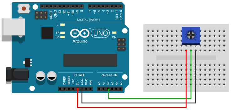
Connecting a potentiometer with an Arduino is very easy. As you see above a potentiometer has three pins. Connect one outer pin to the 5v and another outer pin to the ground. Connect the middle pin to the Arduino analog pin A2.
Potentiometer Arduino Code
In the current configuration, the voltage of the middle pin of the potentiometer varies from 0v to 5v. So you can use the Arduino analogRead() function to read the potentiometer value.
You can use the Arduino analogRead() function to read the potentiometer value. Arduino Uno has a 10-bit ADC on its analog pin. That means it can detect 1,024 (210) discrete analog levels.
In the following sections, I will show three different example
Potentiometer Reading on Serial Monitor
In this section, I will show you how you can see the potentiometer reading on the Arduino serial monitor. Monitoring the potentiometer value on the serial monitor has no practical use. However, it is very useful for understanding how the potentiometer works and how to diagnose potentiometer-related problems.
The below code will show the potentiometer reading on the Arduino serial monitor.
Arduino Potentiometer Code
const int potPin = A2;

void setup() {
  Serial.begin(9600);
}

void loop() {
  int potValue = analogRead(potPin);
  Serial.println(potValue);
  delay(1);
}
Map the Potentiometer Arduino Reading
Arduino UNO has a 10-bit ADC on its analog pin whereas the PWM pin has an 8-bit resolution. That means an analog pin can take input in 1024 levels but the PWM pin only has 256 levels of output.
So if you want to control anything with Arduino PWM using a potentiometer input, (let’s say you want to control the brightness of an LED) you need to map the analog input values (0 to 1023) between 0 to 255.
We can do that using a few lines of code but thankfully Arduino has a built-in function to do that in one line of code.
Here I am talking about the map() function of the Arduino. It requires five arguments to map values.
map(value, fromLow, fromHigh, toLow, toHigh)value – the value you want to map.
fromLow – the lower limit of the value’s current range.
fromHigh – The upper limit of the value’s current range.
toLow – the lower limit of the value’s target range.
toHigh – the upper limit of the value’s target range.
In the below code, I have mapped the potentiometer value from 0 to 1023 to 0 to 255. Upload the below code to your Arduino board, open the serial monitor, and rotate the potentiometer knob to see the output.
Arduino Code
const int potPin = A2;

void setup() {
  Serial.begin(9600);
}

void loop() {
  int potValue = analogRead(potPin);
  int pwmValue = map(potValue, 0, 1023, 0, 255);
  Serial.println(pwmValue);
  delay(1);
}
Control the Brightness of an LED
In this section, I will show you how you can use a potentiometer to control the brightness of an LED.
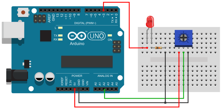
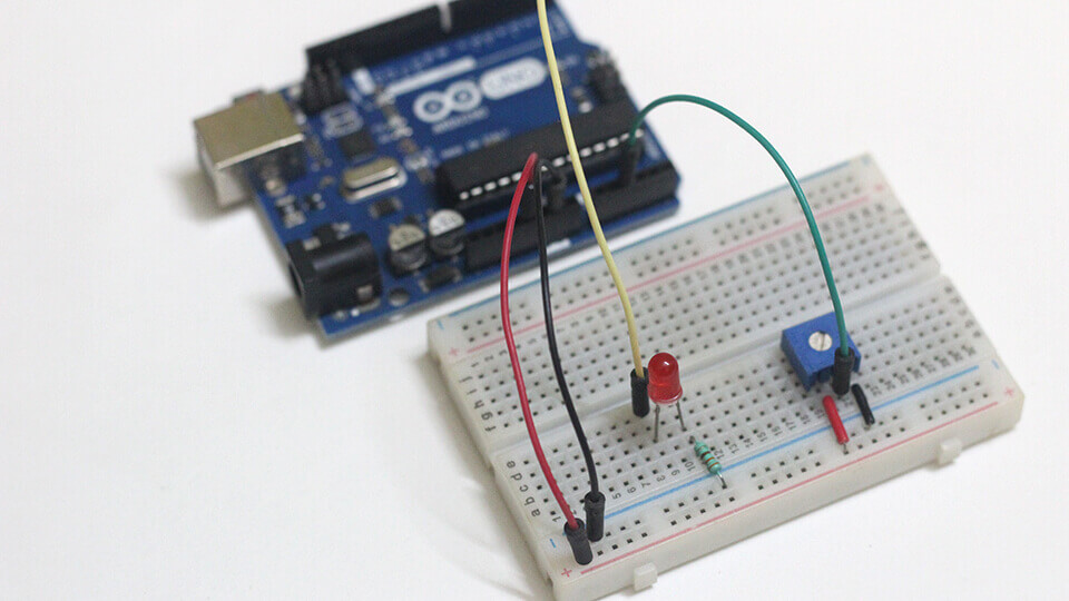
For this example, you need to make a small circuit like below. The potentiometer is connected to the Arduino A5 pin as it was on the previous circuit. Now connect the LED +ve leg to the Arduino PWM pin 3 and connect the -ve leg to the ground using a 220 Ω current limiting resistor.
Arduino Potentiometer Code to Control the Brightness of an LED
const int potPin = A2;
const int ledPin = 3;
int potValue, pwmValue;

void setup() {
  pinMode(ledPin, OUTPUT);
}

void loop() {
  potValue = analogRead(potPin);
  pwmValue = map(potValue, 0, 1023, 0, 255);
  analogWrite(ledPin, pwmValue);
  delay(1);
}
Upload the above code to your Arduino board and rotate the potentiometer knob. you will find that the brightness of the led is increasing/decreasing as you rotate the knob.


Just found you. Just starting to do things with an Arduino and appreciate what you are doing.
Looking to get a pot or two and then have some dc motor control applications I want to do. Also need pot position sensors attached to DC motors or to gear train with mounts so I can see the motor or gear displacement.
Thanks for the help.