Do you ever think about how automatic taps give water when you put your hand beneath them or the magic of smart bulbs that illuminate a room the moment someone enters? In many of these instances, a PIR sensor is the magic behind the scenes.
In this tutorial, you will learn how a PIR motion sensor works and how to connect a PIR sensor to an Arduino. At the end of this tutorial, I will make a cool project that uses a PIR sensor.
Introducing the PIR motion sensor
A PIR sensor (passive infrared sensor) is a type of motion sensor that detects changes in infrared radiation within its field of view. As the name suggests it is a “passive” infrared sensor so it does not emit any type of infrared rays. It only measures the infrared (IR) rays radiating from objects in its field of view.
All living beings and objects contain a certain degree of internal heat and they consistently emit this heat in the form of infrared radiation. When an object moves, the radiation level changes. A PIR sensor identifies a motion by detecting that change in radiation level.
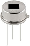
PIR motion sensor is widely used in home security systems, home automation, and smart devices to detect motion. It is very popular in this type of application because of its low price and the accuracy of detecting motion flawlessly. But keep in mind that the PIR can only sense the motion, not the direction of the motion.
How PIR Sensor works
PIR sensors are typically made of a pyroelectric material, which can detect different levels of infrared radiation. If you look closely you will find that there are two rectangular slots inside the sensor. Both the slots have the same cells that can detect the IR levels in their field of view.
When there is no movement both the slots get the same amount of infrared radiation. But when a human body or animal moves in or out of the sensor’s range, there will be a difference in these two sensors’ reading. We can detect any motion by reading this change in voltage.
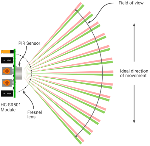
HC-SR501 PIR Sensor Module
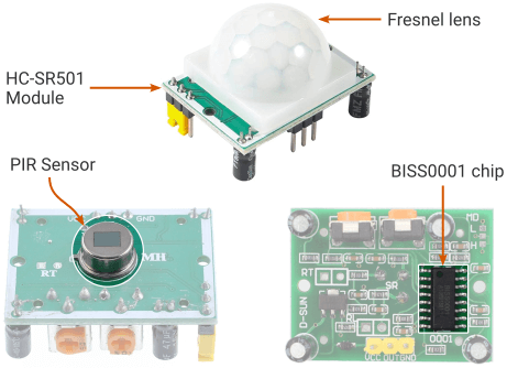
The pyroelectric sensor generates an analog signal, which can be challenging to process. The HC-SR501 PIR sensor module simplifies the process. It uses the BISS0001 chip to convert this analog signal into a digital signal.
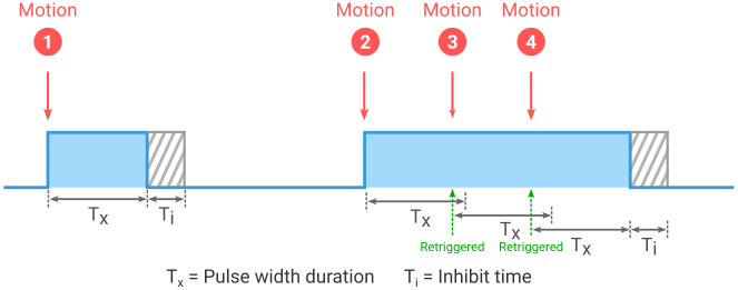
The output goes high when it detects a movement and goes low when the movement stops. The waveform of the output signal of an HC-SR501 module is shown below.
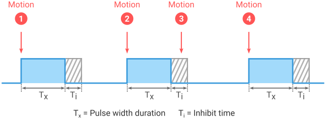
As you see above there are two timeouts associated with the output signal. One is output pulse width (Tx) and another is trigger inhibit timing (Ti). Tx is the time duration for which the pulse remains high after triggering. After every pulse triggering is inhibited for some time. This is called inhibit timing (Ti).
In the HC-SR501 module, there are two trim potentiometers, where one is used to regulate the pulse width (Tx), and the other is used to control the sensitivity of the sensor. You can turn the knob clockwise or anti-clockwise to adjust the pulse width duration and sensitivity.
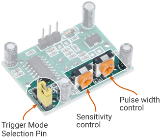
The HC-SR501 module also contains some jumper headers to select between two types of trigger modes – single trigger mode and retrigger mode.
Single trigger mode (L) – In this trigger mode, the output signal goes high upon detecting movement and remains in the high state for a preset period of time. During this time period, the sensor will not react to any further motion. After the specified period, the pulse transits to a low state.
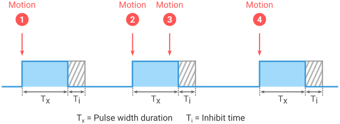
Retrigger mode (H) – In the retrigger mode, the sensor responds to each detected motion. When motion is detected, the output signal goes high and remains in this state for a preset time period (Tx). If the sensor detects another movement within this time period (Tx), the timer resets, and the signal remains high for an additional time period (Tx ms). The pulse will transit to a low state if no further motion is detected within this time period.
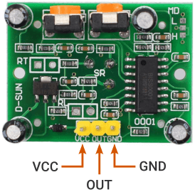
HC-SR501 Module Pinout
HC-SR501 PIR sensor has only three pins – VCC, OUT, and GND. VCC and GND is the power supply pin where the OUT pin provides the output signal from the sensor.
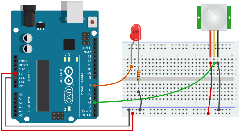
Arduino PIR Sensor Circuit
Connecting a PIR sensor with Arduino is very simple and straightforward. Connect the VCC and GND pin to Arduino 5V and ground pin respectively. Connect the OUT pin to the Arduino pin 3 (any interrupt pin). I also added an LED in the circuit to illuminate when motion is detected.
Remember that the PIR data could be read as a simple digital read or as an interrupt. A simple digital read works for most of the projects but for advanced projects, you should connect the PIR sensor as an interrupt.
PIR Motion Sensor Arduino Code
The code for the PIR sensor could be as simple as a digital read of an Arduino pin. However, it can become more complex for larger projects. I will write and explain codes for a few different scenarios that will help you add the PIR sensor to any project.
Let’s start by simply displaying the waveform of the output pulses in the serial plotter of the Arduino IDE.
Code – Displaying the Waveform
/*
  PIR Sensor data on the Serial Plotter
  Written by : Kishor
  Tutorial : https://www.circuitgeeks.com
*/

const int pirPin = 3;     // pin for the PIR sensor
const int pirState = LOW; // variable for reading the PIR pin status

void setup() {
  // initialize serial communication at 9600 bits per second
  Serial.begin(9600);
  pinMode(pirPin, INPUT); // declare sensor as input
}

void loop() {
  pirState = digitalRead(pirPin); // read input value
  Serial.println(pirState); // print out the state of the button:
  delay(50); // delay in between reads
}
Run the code and open the serial plotter on the Arduino IDE. Wave your hand in front of the sensor to see how it reacts to the motion. Adjust the delay to control the speed of the pulse.
Simply Turn On and Off an LED
The below code will turn on an LED when a motion is detected. The LED will remain on till the pulse is high. It will turn off as soon as the pulse transits to a low state.
/*
  Arduino digitalRead a PIR sensor with LED
  Written by : Kishor
  Tutorial : https://www.circuitgeeks.com
*/

const int ledPin = 7; // pin for the LED
const int pirPin = 3; // pin for the PIR sensor
byte pirState = LOW;  // variable for reading the PIR pin status

void setup() {
  pinMode(ledPin, OUTPUT); // declare LED as output
  pinMode(pirPin, INPUT);  // declare sensor as input
}

void loop() {
  pirState = digitalRead(pirPin); // read input value
  if (pirState == HIGH) {
    digitalWrite(ledPin, HIGH); // turn LED ON
  }
  else {
    digitalWrite(ledPin, LOW); // turn LED OFF
  }
}
In the above program, you have seen that the LED’s on time is completely dependent upon the pulse duration. This could be a limitation in some applications.
Let’s say you want to turn off the LED only when you press a button or you want the LED to remain on for a specific duration irrespective of the pulse duration of the sensor. In these cases, you will need the Arduino interrupt function.
PIR Sensor Arduino Interrupt Code
The below code demonstrates how to use the Arduino interrupt function with the PIR motion sensor. The code will turn on an LED when a motion is detected. It will remain on for the duration set on the program. After that, it will turn off and wait for the next movement.
/*
  Arduino Interrupt with PIR sensor and LED
  Written by : Kishor
  Tutorial : https://www.circuitgeeks.com
*/

const int ledPin = 7; // pin for the LED
const int PIRInterrupt = 3; // pin for the PIR sensor

volatile byte motion = false; // flag

const long onTime = 10000; // LED on time after a motion is detected
unsigned long lastTrigger = 0; // last time the sensor was triggered

void setup() {
  pinMode(ledPin, OUTPUT); // declare LED as output
  pinMode(PIRInterrupt, INPUT); // declare sensor as input
  // Call the motionDetected function when a rising edge is detected
  attachInterrupt(digitalPinToInterrupt(PIRInterrupt), motionDetected, RISING);
}

void loop() {
  if ((millis() - lastTrigger) < onTime && motion == true) {
    // during the onTime period & motion = true
    digitalWrite(ledPin, HIGH); // turn on the LED
  }
  else {
    digitalWrite(ledPin, LOW); // turn off the LED
  }
}

void motionDetected() {
  lastTrigger = millis();
  motion = true;
}
Explaining the Code
First, I declare some variables to use later in the program. I used two constant integer variables to hold the pin number that is connected to the LED and the PIR output pin.
const int ledPin = 7;
const int PIRInterrupt = 3;
I created a variable named motion that I will use as a flag in the program.
volatile byte motion = false;
I also need two other variables to handle the time. The onTime is used to set the duration of how much time the LED will remain on after a motion is detected. The lastTrigger is used to save the last time motion was detected.
const long onTime = 10000;
unsigned long lastTrigger = 0;
In the setup, section I set the LED pin as an output pin and the PIR pin as an input pin.
pinMode(ledPin, OUTPUT);
pinMode(PIRInterrupt, INPUT);
I use the Arduino interrupt function to continuously monitor the output pin of the PIR sensor. Here I use the RISING mode to trigger the function when a rising edge is detected at the interrupt pin.
attachInterrupt(digitalPinToInterrupt(PIRInterrupt), motionDetected, RISING);
The interrupt function needs an ISR (Interrupt Service Routine) that it calls whenever it detects any specific type of changes (e.g. rising or falling etc) in the interrupt pin.
So I created an ISR function named motionDetected at the end of the program. It monitors the last time the sensor was triggered and sets the motion flag to true.
void motionDetected() {
  lastTrigger = millis();
  motion = true;
}
In the loop section, I use the Arduino millis() function to keep track of the time. The LED will turn on from the lastTrigger time till the onTime duration is over. After that, it will turn off and wait for the next motion.
if ((millis() - lastTrigger) < onTime && motion == true) {
  digitalWrite(ledPin, HIGH);
}
else {
  digitalWrite(ledPin, LOW);
}
Simple Gesture Control Device
You can add the PIR sensor to your smart home project to create a simple gesture-control device that starts and ends a task on every alternative motion.
For the demonstration, I will again use an LED. It will turn on and off on every alternative motion.
/*
  Arduino Interrupt with PIR sensor and LED
  Written by : Kishor
  Tutorial : https://www.circuitgeeks.com
*/

const int ledPin = 7; // pin for the LED
const int PIRInterrupt = 3; // pin for the PIR sensor
volatile byte state = LOW; // variable to hold the LED State

void setup() {
  pinMode(ledPin, OUTPUT); // declare LED as output
  pinMode(PIRInterrupt, INPUT); // declare sensor as input
  // Call the motionDetected function when a rising edge is detected
  attachInterrupt(digitalPinToInterrupt(PIRInterrupt), motionDetected, RISING);
}

void loop() {
  // we dont need anything in the loop
}

void motionDetected() {
  state = !state; // change the LED state
  digitalWrite(ledPin, state); // assign the LED state to the LED.
}
Buzzer with PIR motion sensor
Here you will see how to add a buzzer in the circuit that will generate a sound and light up the LED when detecting an object. You can install the PIR sensor in the backyard so that you would get informed when anyone traces pass into your property.
If you are not familiar with buzzers you can read my Arduino buzzer tutorial. Also, you could use a bulb (120 Volts) instead of an LED by following my Arduino Relay Tutorial.
Add a Buzzer in the Circuit
The circuit remains unchanged as described earlier, I simply add a buzzer to the circuit. Connect the positive (+) pin of the buzzer to Arduino pin 7 and the other pin to the ground. You can add a resistor below 470 ohm in series with the buzzer to reduce its volume. The higher the resistance lower the volume.
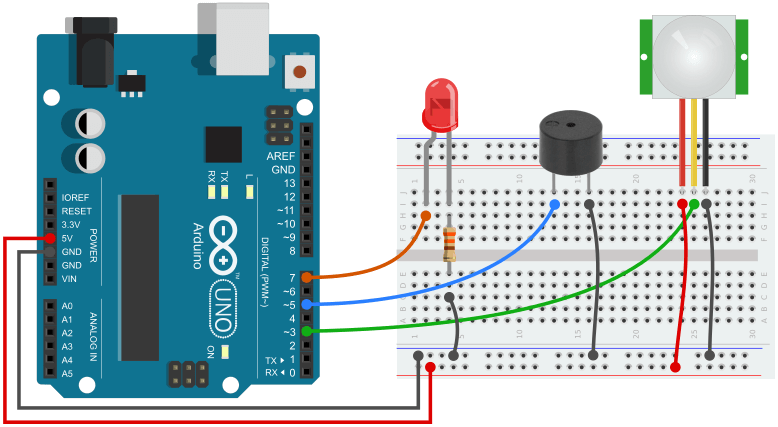
PIR Sensor Buzzer Siren Code
The below code will turn on an LED and generate a sound for 5 seconds every time it detects a motion.
/*
  Arduino PIR Interrupt with Buzzer and LED
  Written by : Kishor
  Tutorial : https://www.circuitgeeks.com
*/

const int PIRInterrupt = 3; // pin for the PIR sensor
const int buzzer = 5; // pin for the Buzzer
const int ledPin = 7; // pin for the LED
const int freqInterval = 10;

volatile byte motion = false; // flag

const long onTime = 5000; // LED and Buzzer on time after a motion is detected
unsigned long lastTrigger = 0; // last time the sensor was triggered
unsigned long lastFreqChange = 0; // last time the frequency was changed
int freq = 635;

void setup() {
  pinMode(ledPin, OUTPUT); // Set the LED pin as Output
  pinMode(buzzer, OUTPUT); // Set the Buzzer pin as Output
  digitalWrite(ledPin, LOW);
  pinMode(PIRInterrupt, INPUT);
  // call the motionDetected function when a rising edge is detected
  attachInterrupt(digitalPinToInterrupt(PIRInterrupt), motionDetected, RISING);
}

void loop() {
  if ((millis() - lastTrigger) < onTime && motion == true) {
    // during the interval period & if motion is true
    digitalWrite(ledPin, HIGH); // turn on the LED
    buzzerSiren(); // call the buzzerSiren function
  }
  else {
    digitalWrite(ledPin, LOW); // turn off the LED
    noTone(buzzer); // turn off the Buzzer
    freq = 635;
  }
}

void motionDetected() {
  lastTrigger = millis();
  motion = true;
}

void buzzerSiren() { // Function for the Buzzer sound
  tone(buzzer, freq);

  if (millis() - lastFreqChange > freqInterval) {
    lastFreqChange = millis();
    freq++;
  }
  if (freq > 912)
    freq = 635;
}


