In this tutorial, you will learn how to control a dot matrix LED display with MAX7219 using an Arduino board. I will use an 8×8 as well as an 8×32 dot matrix display in this tutorial to display text, characters, and scrolling texts.
Table of Contents
MAX7219 Dot Matrix LED Module
8×8 dot matrix LED display comes with or without a MAX7219 driver. MAX7219 is a very popular LED driver for 8×8 LED matrix display. If you purchase the 8×8 LED matrix display and MAX7219 IC separately you need to connect them together. In this project, I will use a MAX7219 Dot Matrix LED Module to avoid ugly wiring.
Below you can see an 8×8 dot matrix LED display with a MAX7219 driver.
The most common MAX7219 LED display is the generic module which has 8×8 LED and the F-16 module which has 8×32 LEDs. Basically, the F-16 module is four MAX7219 8×8 matrices connected serially.
LED Matrix Multiplexing
To control 8×8 i.e. 64 LEDs we need 64 data pins. But with the help of LED multiplexing, we can control the same amount of LED using only 16 data pins.
In this process, all the cathodes are connected together row-wise and all the anode is connected together column-wise.
Below you can see the schematic diagram of an 8×8 LED matrix multiplexing.
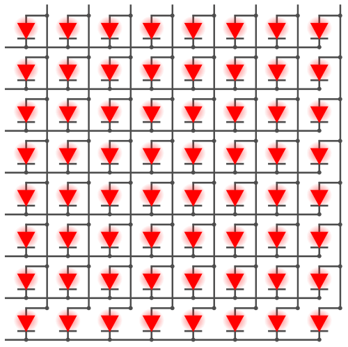
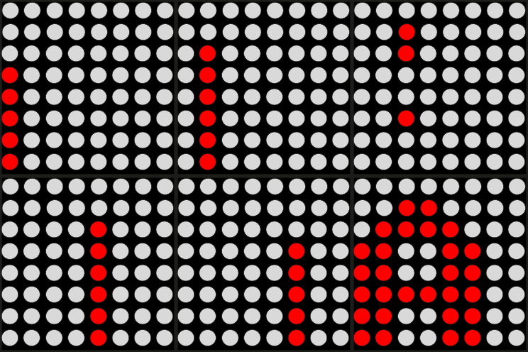
In the multiplexing process, we activate each column for a very short period of time and turn on the necessary LED for that row. We will do the same process for every column. The columns are switched so fast that the normal human eye sees it as a complete picture.
For better understanding, I create an animation that shows how the letter “A” is printed on an 8×8 LED matrix display.
How LED Matrix is Connected to MAX7219
In the previous section, you see that we need 16 data pins to control an 8×8 LED matrix when multiplexing. We can use a LED driver IC to reduce the pin number even more. For the 8×8 LED Matrix display, we have a MAX7219 LED driver. MAX7219 LED driver is a very popular LED driver for 8×8 LED matrix display.
Below you will see the pinout of a MAX7219 IC.
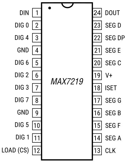
It comes with 24-Pin DIP and SO packages. It has 16 parallel data pins to control LEDs. It has SPI interfaces that mean you can connect multiple MAX7219 modules over the same line. It takes serial data from the MCU and converts it to parallel data to control LEDs. So you only need three pins from your MCU to control an 8×8 LED matrix display with MAX7219.
If you get a separate MAX7219 IC you can connect it to an 8×8 LED matrix using below circuit diagram.
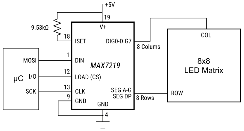
To avoid complex wiring get a LED matrix with the MAX7219 breakout board.
Pinout of MAX7219 Module
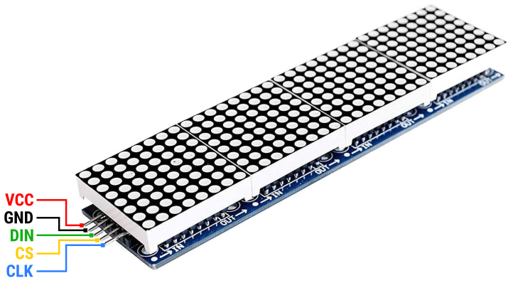
A Generic 8×8 module or an F16 8×32 module have the same pin configuration. They have five pins on each side. One side is for the input and the other side is for output. On the input side, it can take instructions from MCUs and on the output side, it can connect with another display module.
On the input side, it has VCC, GND, DIN, CS, and CLK and on the output side, it has VCC, GND, DOUT, CS, and CLK.
In the below image you can see the pinout of a Generic module and F16 module.
Connect with Arduino
The most common sizes for the MAX7219 LED matrix are 8×8 and 8×32. The MAX7219 LED matrix display has five pins VCC, GND, DIN, CS, and CLK. It uses the SPI communication protocol. So you can connect it to your Arduino board like any other SPI module.
In this tutorial, I will use an Arduino UNO board to control an 8×8 and 8×32 MAX7219 board.
Arduino has dedicated pins (hardware SPI) for SPI communication but you can also use any three arbitrary digital pins (software SPI) for communication. Remember that hardware SPI is much faster than software SPI.
In the below diagram an Arduino Uno is connected to an F16 module using hardware SPI pins.
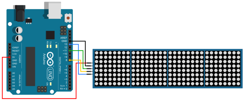
Here you can see that I connect the VCC pin to the Arduino 5v pin and GND to the Arduino Ground pin. Then I connect the DIN pin to Arduino pin 11 which is the MOSI pin and the CLK pin to Arduino pin 13 which is the SCK pin. The chip select (CS) pin is connected to pin no 8 in Arduino.
You can connect a MAX7219 Generic module in the same way.
Arduino Code for MAX7219 LED Matrix Display
We have a few popular libraries to control MAX7219 LED matrix displays with Arduino. MD_MAX72XX, MD_Parola, LedControl, MAXmatrix etc.
In this tutorial, I am going to use MD_MAX72XX and MD_Parola library to control the MAX7219 display. For that, we need to install those libraries in our Arduino IDE. To install these libraries, navigate to Tools > Manage Libraries and search for MD_MAX72XX and MD_Parola by MajicDesigns. Find the correct library and Install it.
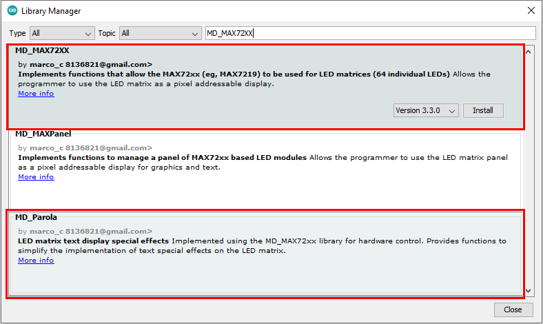
That’s it, now you can write a program to control the MAX7219 display. In the section below I will write and explain some programs to print text, scroll text and print some custom characters on the display.
Print Simple Text
For the first experiment, I will print a simple text on the display. But before jumping into the programming you need to know some basic parameters used in MD_MAX72XX and MD_Parola library and change it according to your need.
The first thing you need to change is the definition of hardware type. The below line defines the type of hardware you use.
#define HARDWARE_TYPE MD_MAX72XX::FC16_HWThe most common hardware types are the Generic module and FC16 module. The generic module comes with a green board and a DIP 24 Pin MAX7219 IC. FC16 module comes with a blue board and an SOP MAX7219 IC under the LED matrix.
If you have a Generic module use GENERIC_HW, and if you have an F16 module use FC16_HW.
Then you have #define MAX_DEVICES. Here you need to put the number of 8×8 dot matrix displays you use.
A single MAX7219 IC can control only one 8×8 LED matrix and counts as one device. If you have an FC16 8×32 LED matrix module, you have four 8×8 LED matrices with four MAX7219 IC together. So you must set MAX_DEVICES to 4. For an 8×8 Generic module, you must set MAX_DEVICES to 1.
Then you have to select between Hardware SPI and Software SPI. Hardware SPI is much faster than Software SPI but for a small display, it hardly matters.
If you prefer Software SPI, you can create a new instance of the MD_Parola class like this –
MD_Parola myDisplay = MD_Parola(HARDWARE_TYPE, DATA_PIN, CLK_PIN, CS_PIN, MAX_DEVICES);Here you need to define DATA_PIN, CLK_PIN, and CS_PIN before.
And if you prefer Hardware SPI, you can create a new instance like this –
MD_Parola myDisplay = MD_Parola(HARDWARE_TYPE, CS_PIN, MAX_DEVICES);Here you need to define CS_PIN above that line.
Now change the below code according to your hardware type and pin uses and upload the code to your Arduino board.
#include <MD_Parola.h>
#include <MD_MAX72xx.h>
#include <SPI.h>

#define HARDWARE_TYPE MD_MAX72XX::FC16_HW
#define MAX_DEVICES 4
#define CS_PIN      8

MD_Parola myDisplay = MD_Parola(HARDWARE_TYPE, CS_PIN, MAX_DEVICES);

void setup() {
  myDisplay.begin();
  myDisplay.setIntensity(0);
  myDisplay.displayClear();
}

void loop() {
  myDisplay.setTextAlignment(PA_CENTER);
  myDisplay.print("Hello!");
}
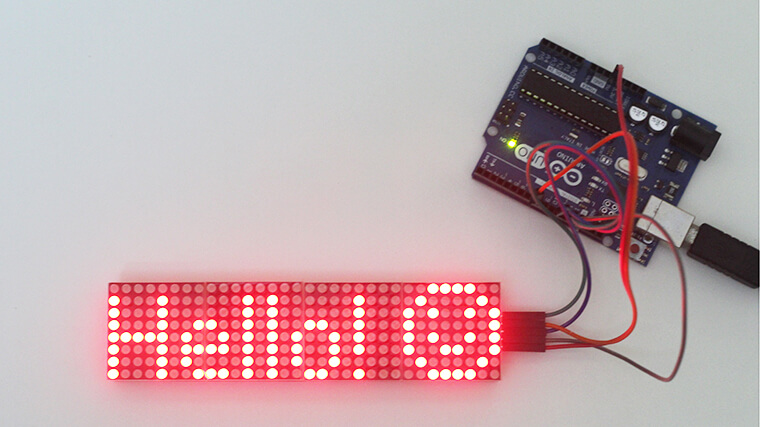
You will get an output like this –
Image of the original F16 display
Explaining the Code
First I Include the necessary library.
#include <MD_Parola.h>
#include <MD_MAX72xx.h>
#include <SPI.h>
Then I defined the hardware type and the number of devices. I am using an 8×32 F16 module so I set the hardware type to FC16_HW and MAX_DEVICES to 4.
#define HARDWARE_TYPE MD_MAX72XX::FC16_HW
#define MAX_DEVICES 4
I set the CS pin to 8 as I connect the CS pin to Arduino pin number 8.
#define CS_PIN 8Then I create a new instance of the MD_Parola class with the MD_Parola() function.
This function requires three parameters, the first is the hardware type, the second is the CS pin and the third is the maximum number of connected devices.
MD_Parola myDisplay = MD_Parola(HARDWARE_TYPE, CS_PIN, MAX_DEVICES);In the setup() section, I initialize the object with the begin() function. We can set the brightness of the display with the function setIntensity(). We can set the brightness level from 0 (minimum intensity) to 15 (maximum intensity). displayClear() will clear the display.
void setup() {
  myDisplay.begin();
  myDisplay.setIntensity(0);
  myDisplay.displayClear();
}
In the loop() section, I first align the text using the setTextAlignment() function. You can align the text to the right, left, or center with PA_RIGHT, PA_LEFT, and PA_CENTER respectively.
Then we have a print()function to print text/string and numbers. If you want to print text/string you have to put it in quotation (“ ”) mark. When you print numbers no quotation mark is needed.
void loop() {
  myDisplay.setTextAlignment(PA_CENTER);
  myDisplay.print("Hello!");
}
Scrolling Text
A typical 8×32 F16 display module can show only 6-8 characters at once. For a large text, we need to use scrolling text effects to show the complete text. The below example will show you how to scroll text on a LED matrix display.
#include <MD_Parola.h>
#include <MD_MAX72xx.h>
#include <SPI.h>

#define HARDWARE_TYPE MD_MAX72XX::FC16_HW
#define MAX_DEVICES 4
#define CS_PIN      8
MD_Parola myDisplay = MD_Parola(HARDWARE_TYPE, CS_PIN, MAX_DEVICES);

void setup() {
  myDisplay.begin();
  myDisplay.setIntensity(0);
  myDisplay.displayClear();
  myDisplay.displayScroll("Hello World!", PA_CENTER, PA_SCROLL_LEFT, 100);
}

void loop() {
  if (myDisplay.displayAnimate()) {
    myDisplay.displayReset();
  }
}
Explaining the Code
You can see that the code before the setup() section is the same as the previous example. It will remain the same for all the examples below, but sometimes you will find some variable definition in this section of the code.
Now coming to the setup() section I first initialize the object with the begin() function. We can set the brightness of the display with the function setIntensity(). displayClear() will clear the display.
Then I use the displayScroll() function to display the scrolling text effect. The function needs four arguments –
displayScroll(pText, align, textEffect, speed)pText – this is the text you want to scroll on the display. As it is a text string you have to wrap it under quotation (“ ”) mark.
align – this will align the text. we can use the same align option we used before, i.e. PA_RIGHT, PA_LEFT, and PA_CENTER.
textEffect – sets the direction of scrolling. You can use PA_SCROLL_LEFT, PA_SCROLL_RIGHT, PA_SCROLL_UP, PA_SCROLL_DOWN to scroll from left, right, up, and down respectively.
speed – speed will determine the speed of the effect in milliseconds.
So, you can understand that the below code will show a scrolling text “Hello!” Which will scroll from left to right with an interval of 100ms.
myDisplay.displayScroll("Hello!", PA_CENTER, PA_SCROLL_LEFT, 100);Other Text Animations
MD_MAX72XX and MD_Parola have some awesome built-in functions to display animated text on the MAX7219 LED matrix display. In the below example, I will show how to use those functions to create an animated text display.
#include <MD_Parola.h>
#include <MD_MAX72xx.h>
#include <SPI.h>

#define HARDWARE_TYPE MD_MAX72XX::FC16_HW
#define MAX_DEVICES 4

//Hardware SPI Arduino UNO
// CLK Pin  > 13 SCK
// Data Pin > 11 MOSI

//#define CLK_PIN   4
//#define DATA_PIN  2
#define CS_PIN      8

// Hardware SPI connection
MD_Parola myDisplay = MD_Parola(HARDWARE_TYPE, CS_PIN, MAX_DEVICES);
// Arbitrary output pins
//MD_Parola myDisplay = MD_Parola(HARDWARE_TYPE, DATA_PIN, CLK_PIN, CS_PIN, MAX_DEVICES);

int i = 0;

textEffect_t texteffect[] = {
  PA_WIPE,
  PA_WIPE_CURSOR,
  PA_OPENING_CURSOR,
  PA_CLOSING_CURSOR,
  PA_BLINDS,
  PA_MESH,
  PA_OPENING,
  PA_CLOSING,
  PA_SCAN_VERT,
  PA_DISSOLVE,
  PA_RANDOM,
  PA_PRINT,
  PA_SCROLL_RIGHT,
  PA_SCROLL_LEFT,
  PA_GROW_UP,
  PA_GROW_DOWN,
  PA_SCROLL_UP,
  PA_SCROLL_DOWN,
  PA_SCROLL_UP_RIGHT,
  PA_SCROLL_UP_LEFT,
  PA_SCROLL_DOWN_RIGHT,
  PA_SCROLL_DOWN_LEFT,
};
void setup() {
  myDisplay.begin();
  myDisplay.setIntensity(0);
  myDisplay.setTextAlignment(PA_CENTER);
  myDisplay.setSpeed(100);
  myDisplay.setPause(1000);
  myDisplay.displayClear();
}

void loop() {
  if (myDisplay.displayAnimate()) {
    if (i < sizeof(texteffect)) {
      i++;
    }
    else {
      i = 0;
    }
    myDisplay.displayText("Hello", myDisplay.getTextAlignment(), myDisplay.getSpeed(), myDisplay.getPause(), texteffect[i], texteffect[i]);
    myDisplay.displayReset();
  }
}
Explaining the Code
Here you can see that I initialize an integer variable i and set the value to 0. Then create an array to hold all the built-in keywords for the text effect.
In the setup() section, I first initialize the display object and then set the intensity and align the text. Then I set the speed for the animation and pause time for the text. And finally, clear the display.
In the loop section, I display all the text effects one by one using the displayText() function.
This function has 6 parameters.
displayText(pText, align, speed, pause, effectIn, effectOut);pText – This is the text you want to display on the screen.
align – The alignment of the display.
speed – Speed of the animation in ms.
pause – duration of the text to be displayed on the screen.
effectIn – Effect of the text when it comes into the display.
effectOut – Effect of the text when it goes out of the display.
You can use this function by simply putting the parameter into the function like –
myDisplay.displayText("Hello", PA_CENTER, 100, 1000, PA_WIPE, PA_WIPE);Or you can use it like this
myDisplay.displayText("Hello", myDisplay.getTextAlignment(), myDisplay.getSpeed(), myDisplay.getPause(), texteffect[i], texteffect[i]);And set the texteffect(), setTextAlignment(), setSpeed() and setPause() before the setup section like the above example.
Custom Character
Besides normal text and numbers, you can also display custom characters to a MAX7219 LED matrix display.
In the below code I will show how to print custom characters to an LED matrix display.
#include <MD_MAX72xx.h>
#include <SPI.h>

#define  delay_t  50  // in milliseconds

#define HARDWARE_TYPE MD_MAX72XX::FC16_HW
#define MAX_DEVICES 4

//Hardware SPI Arduino UNO
// CLK Pin  > 13 SCK
// Data Pin > 11 MOSI

#define CS_PIN    8

// Hardware SPI connection
MD_MAX72XX mx = MD_MAX72XX(HARDWARE_TYPE, CS_PIN, MAX_DEVICES);

byte heart[8] = {0x00, 0x66, 0xFF, 0xFF, 0xFF, 0x7E, 0x3C, 0x18};
byte face[8] = {0x3C, 0x42, 0xA5, 0x81, 0xA5, 0x99, 0x42, 0x3C};
byte face2[8] = {0x00, 0x24, 0x24, 0x24, 0x00, 0x42, 0x3C, 0x00};
byte arrow[8] = {0x18, 0x0C, 0x06, 0xFF, 0xFF, 0x06, 0x0C, 0x18};

void setup() {
  mx.begin();
  mx.control(MD_MAX72XX::INTENSITY, 0);
  mx.clear();
  }

void loop() {
  drawShape();
}

void drawShape() {
  for (int i = 0; i <= 7; i++) {
    mx.setRow(0, 0, i, heart[i]);
  }
  delay(delay_t);
  for (int i = 0; i <= 7; i++) {
    mx.setRow(1, 1, i, face[i]);
  }
  delay(delay_t);
  for (int i = 0; i <= 7; i++) {
    mx.setRow(2, 2, i, face2[i]);
  }
  delay(delay_t);
  for (int i = 0; i <= 7; i++) {
    mx.setRow(3, 3, i, arrow[i]);
  }
  delay(delay_t);
}
Explaining the Code
To print a custom character you need to have the bite code for that character first. Creating byte code is very simple. For example, I will create a bite map for the Heart shape.
For that, we have to go through row-wise and write 0 to turn off an LED and write 1 to turn on an LED.
So for the first row, we get 0000000, for the second row we get 01100110. When we complete all the rows it will look like this –
00000000
01100110
11111111
11111111
11111111
01111110
00111100
00011000
So the byte code for this will be {B00000000, B01100110, B11111111, B11111111, B11111111, B01111110, B00111100, B00011000}.
And you can store it in an array like this – byte arrow[8] = {B00000000, B01100110, B11111111, B11111111, B11111111, B01111110, B00111100, B00011000};
You can convert the binary value to hexadecimal and use it like this –
byte arrow[8] = {0x18, 0x0C, 0x06, 0xFF, 0xFF, 0x06, 0x0C, 0x18};
There are some online and offline tools available that can help you to generate binary and hexadecimal code for you. You can use the PixelToMatrix desktop application.
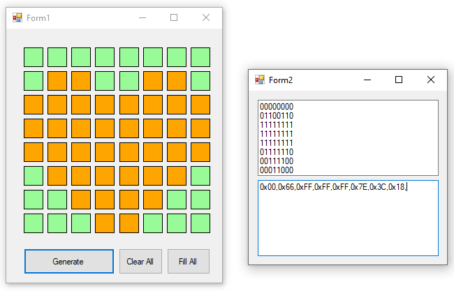
Or you can use any of the online tools below.
jorydotcom.github.io/matrix-emoji/
gurgleapps.com/tools/matrix
Now come to the example code and you will find that I create four arrays for the four custom characters above the setup section.
byte face[8] = {0x3C, 0x42, 0xA5, 0x81, 0xA5, 0x99, 0x42, 0x3C};
byte face2[8] = {0x00, 0x24, 0x24, 0x24, 0x00, 0x42, 0x3C, 0x00};
byte heart[8] = {0x00, 0x66, 0xFF, 0xFF, 0xFF, 0x7E, 0x3C, 0x18};
byte arrow[8] = {0x18, 0x0C, 0x06, 0xFF, 0xFF, 0x06, 0x0C, 0x18};
In the setup() section, I initialize the display object, set the intensity of the display, and clear the display.
In the loop section, I call a function drawShape() that I defined after the loop section.
In the definition of drawShape() function, I use setRow() function to show the custom character. This function has four parameters.
setRow(startDev, endDev, r, value);startDev – from which division you want to display the character.
endDev – at which division you want to stop.
r – no of the row which is to be set.
value – bit map of that row.
So you can understand that mx.setRow(0, 0, 0, B11111111); or mx.setRow(0, 0, 0, 0xFF); will turn on all the LEDs of the first row of the first block. In the same way, we can fill the other row and display what we need.
For example, we can display the Heart symbol at the first block using the below code.
mx.setRow(0, 0, 0, 0x00);
mx.setRow(0, 0, 1, 0x66);
mx.setRow(0, 0, 2, 0xFF);
mx.setRow(0, 0, 3, 0xFF);
mx.setRow(0, 0, 4, 0xFF);
mx.setRow(0, 0, 5, 0x7E);
mx.setRow(0, 0, 6, 0x3C);
mx.setRow(0, 0, 7, 0x18);
Or you can use an array to reduce the number of line uses.
for (int i = 0; i <= 7; i++) {
    mx.setRow(0, 0, i, heart[i]);
  }
And define the heart[] before the setup section.
Using the same way I will print a heart, two different faces, and an arrow symbol inside the drawShape() function. So when the function is called, these four symbols will display.
Summary
In this tutorial, you have learned about the MAX7219 LED matrix display and how to connect it with Arduino. I hope you find this tutorial very useful. To get more content like this subscribe to our weekly newsletter.
Also, use the comment section below to share your ideas and projects related to the MAX7219 LED matrix display.


Hello, I don´t know if this post is still active but I have a question:
All the samples and tutorials that I found for scrolling a text through my display are very clear and work on my circuits as standalone but they are all based on a fixed text or a simple loop without any program functions. What if I want to scroll different text strings at different conditions in my program? A simple while loop in my sketch makes all the Parola statements stop or scroll the display. I do not find any sample code which shows how to make all Parola functionality flexible to use it like a “print” command if I ever want to output something scrolling on my display. Can you help me with some kind of function() that I call inside of my sketch whenever I need it?