Light Dependent Resistor or LDR is basically a photoresistor. That means its resistance is dependent on the amount of light it gets. We can use an LDR to detect the light level of the environment. If you want a cheap solution to detect day and night LDR would be a good choice.
In this tutorial, I will use an LDR to sense the light of the ambiance. I will show you how to turn on an electric bulb when the LDR senses darkness in the room.
Table of Contents
How LDR Works
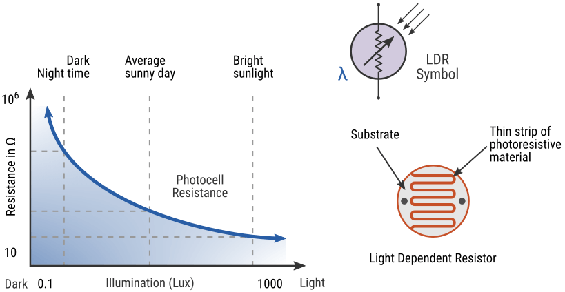
An LDR is built with a zigzag track of photo-sensitive material (photoresistor). When the light falls on the photoresistor, the resistance of the photoresistor decreases. While in the dark, the sensor can have resistance as high as a thousand or mega ohms. In the light, its resistance drops to a few hundred ohms. The below diagram shows the LDR resistance vs illumination characteristic curve.
How to connect an LDR to Arduino
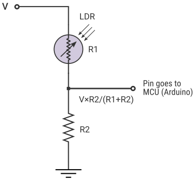
To connect an LDR with the Arduino you need to make a voltage divider configuration like below. Here I will use a 100K ohm resistor. You may need different resistor values depending on your LDR.
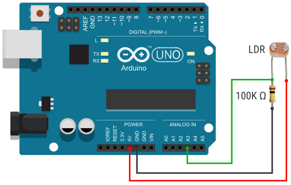
Now connect the LDR output to any Analog pin on your Arduino board. See the below circuit diagram for reference.
You can see that one leg of the LDR is connected to the +5v pin on the Arduino and another leg is connected to the Analog pin A3. The same leg which is connected to the analog pin is connected to the ground through a 100K Ω resistor.
Arduino LDR Code
You can read the LDR sensor data using Arduino’s analogRead() function. Arduino’s analog pin converts the analog sensor data (voltages between 0-5v) to 1024 discrete levels and we can read it using the analogRead() function.
In the below section, I will show you how to write Arduino code for LDR. First I will show you how to read the raw sensor data, then I will show you how you can use that data to make a decision (turn on a light in a dark environment).
Reading The raw Sensor Value
Reading the analog sensor value of an LDR is very important because different LDR may give different readings in the same lighting conditions. So before using an LDR in any project check the raw sensor data.
The below code will show the raw sensor data on Arduino serial monitor. Check the sensor data in different light conditions (in light and dark environments).
Arduino Code
const int ldrPin = A3;
int ldrValue = 0;

void setup() {
  Serial.begin(9600);
}

void loop() {
  ldrValue = analogRead(ldrPin);
  Serial.println(ldrValue);
  delay(20);
}
Explaining the Code
Here you can see that I create a constant integer ldrPin to hold the Arduino pin number connected to the LDR and an integer ldrValue to hold the LDR sensor data.
Then in the setup section, I started a serial communication at a 9600 bud rate.
In the loop section, I read the sensor value using analogRead() function and store that data in the variable ldrValue. Then in the next line, I use serial.print() function to print the sensor data.
Turn on an LED When it is Dark
From the above section, you have found that in a dark environment the LDR sensor reading is near about 10 – 20 (can be different in your LDR). So here I will turn on an LED if the LDR reading is less than 20 otherwise I will turn off the LED.
For this experiment, you need to add a LED to your existing circuit. You can add an LED to the Arduino using the below circuit or you can follow my detailed Arduino LED tutorial.
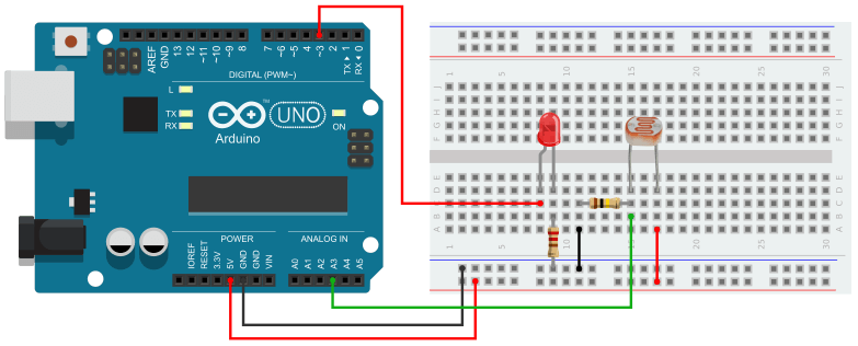
Arduino Code
The below code will turn on the LED when it is dark and turn off the LED when it is bright. Upload the code to your Arduino board and change the lighting condition of your environment and see the output.
const int ldrPin = A2;    // select the input pin for the potentiometer
const int ledPin = 11;    // select the pin for the LED
int ldrValue = 0;   // variable to store the value coming from the sensor

void setup() {
  // declare the ledPin as an OUTPUT:
  pinMode(ledPin, OUTPUT);
}

void loop() {
  ldrValue=analogRead(ldrPin);
  if(ldrValue > 20)
  digitalWrite(ledPin,HIGH);
  else
  digitalWrite(ledPin,LOW);
  delay(100);
}
Explaining the Code
Here I create two constant integers to hold the LDR pin number and LED pin number and an integer variable to hold the LDR sensor data.
In the setup section, I set the LED pin as an output pin. Then in the loop section, I read the sensor value and store that data in the variable ldrValue. Then I create an If else condition, if the ldrValue is greater than 20 then turn on the LED else turn off the LED.
Controlling AC Light Using Arduino, LDR, and Relay
The relay is an electromechanical switch. It is used to turn on and off an appliance working on high voltage AC/DC using a 5v input. When the Arduino supplies a 5v the relay switch will turn on otherwise it will remain off.
In this tutorial, I am using a 5v relay to turn on an electric bulb when the LDR senses a darkness in the room.
High Voltage Warning:Before we continue with this tutorial, I will warn you that this project involves high voltages. Incorrect or improper use could result in serious injuries or death. So please take all necessary precautions and turn off all the power supplies before working on the circuit. I take no responsibility for any of your actions. |
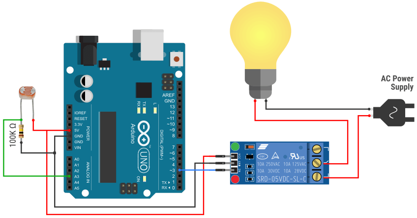
For this tutorial, you have to make a small circuit like below. Here you can see that the LDR is connected as it was connected before, but there are two new components in the circuit – a relay module and an electric bulb.
The relay has three pins on the control side – VCC, Ground, and Input pin. Connect the VCC to the Arduino 5v pin, the Ground pin to the Arduino ground pin, and the Input pin to the Arduino digital pin 3.
On the output side, it has three pins – NC, COM, and NO. Here you have to work with a high-volt AC line. Use a plug to connect with the AC line. Connect the neutral line directly to the bulb. And the phase line goes to another point bulb through the relay switch. The common pin is connected to the bulb and the NO pin is connected to the phase line from the plug.
Arduino Code
The hardware setup is done and now we are ready to program our Arduino board. The below code will turn on the bulb when it is dark and turn off the bulb when it is bright.
int ldrPin = A3;   // select the input pin for ldr
int ldrValue = 0;  // variable to store the value coming from the sensor
int relayPin = 3;  // select the relay control pin

void setup() {
  pinMode(relayPin, OUTPUT); //pin connected to the relay
}

void loop() {
  // read the value from the sensor:
  ldrValue = analogRead(ldrPin);

  if (ldrValue > 20) //setting a threshold value
    digitalWrite(relayPin, HIGH); //turn relay ON
  else
    digitalWrite(relayPin, LOW);  //turn relay OFF
  delay(100);
}
Explaining the Code
The code and logic are almost the same as the previous one. The only difference is that here I use the relay pin instead of the LED. So when the ldrValue is greater than 20 Arduino sends a HIGH signal to the relay control pin. It will trigger the relay switch and the bulb will turn on.


