LEDs are cool RGB LEDs are even cooler. RGB LEDs can display a variety of colors without wiring multiple color LEDs at once. RGB LED has three different color LEDs in one package. So you can mix up this base color to create any color you want.
In this Arduino tutorial, you will learn what RGB LED is and how to use an RGB LED with the Arduino Board.
Table of Contents
How RGB LED Works
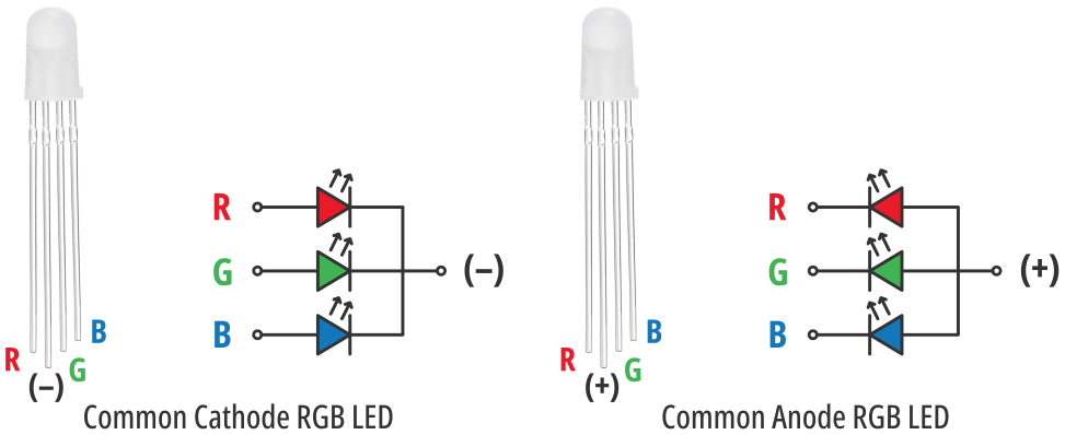
RGB led is basically a combination of three LEDs (Red, Green, and Blue) in one package. It looks very similar to the normal LED light except that an RGB LED has four legs, a common cathode or anode, and another three legs for red, green, and blue LEDs.
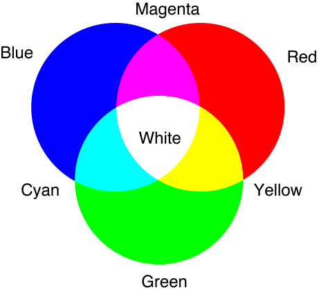
It has three primary colors red, green, and blue and we can mix those colors to make other colors. For example, if you mix red and green you will get yellow color, and if you mix red and blue light you will get magenta color, etc.
You can also control the intensity of each individual LED using an Arduino PWM signal. Each led can have 256 different intensity levels as the Arduino generates an 8-bit PWM signal. So approximately 16 million (2563) colors can be generated.
Connect an RGB LED to Arduino
Connecting an RGB LED with an Arduino is very simple. Here I will show you how to connect a common cathode RGB LED to an Arduino Uno Board.
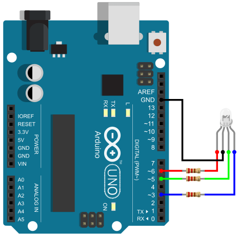
From the above image, you can see that I connect the common cathode pin to the ground pin and connect the other three pins to the Arduino PWM output pin – 3, 5, and 6 using three 220 Ohm (Ω) resistors.
You can use any digital pin if you want to use only the primary colors (red, green, and blue) and combination of those colors (cyan, yellow, and magenta).
Arduino RGB LED Programming
Programming for the RGB LED is very similar to Arduino LED programming. You can use Arduino digitalWrite() or analogWrite() function to control the color of the RGB LED. In the below example, I will use the Arduino digitalWrite() function to create different color outputs.
Arduino Code
const int redPin = 3;
const int greenPin = 5;
const int bluePin = 6;

void setup() {
  pinMode(redPin, OUTPUT);
  pinMode(greenPin, OUTPUT);
  pinMode(bluePin, OUTPUT);
}

void loop() {
  // Color Red
  digitalWrite(redPin, HIGH);
  digitalWrite(greenPin, LOW);
  digitalWrite(bluePin, LOW);
  delay(1000);
  // Color Green
  digitalWrite(redPin, LOW);
  digitalWrite(greenPin, HIGH);
  digitalWrite(bluePin, LOW);
  delay(1000);
  // Color Blue
  digitalWrite(redPin, LOW);
  digitalWrite(greenPin, LOW);
  digitalWrite(bluePin, HIGH);
  delay(1000);
  // Color Yellow
  digitalWrite(redPin, HIGH);
  digitalWrite(greenPin, HIGH);
  digitalWrite(bluePin, LOW);
  delay(1000);
  // Color Cyan
  digitalWrite(redPin, LOW);
  digitalWrite(greenPin, HIGH);
  digitalWrite(bluePin, HIGH);
  delay(1000);
  // Color Magenta
  digitalWrite(redPin, HIGH);
  digitalWrite(greenPin, LOW);
  digitalWrite(bluePin, HIGH);
  delay(1000);
}
Get More Color Using the Arduino PWM Function
In the below example, I will use the analogWrite() function to create different colors besides the base colors. But for that, you need to have the R-G-B values of the desired color. You can find any color of your choice and its R-G-B values using these online tools below.
rapidtables.com/web/color/RGB_Color.html
w3schools.com/colors/colors_picker.asp
Arduino Code
const int redPin = 3;
const int greenPin = 5;
const int bluePin = 6;

void setup() {
  pinMode(redPin, OUTPUT);
  pinMode(greenPin, OUTPUT);
  pinMode(bluePin, OUTPUT);
}

void loop() {
  // Color Red
  analogWrite(redPin, 255);
  analogWrite(greenPin, 0);
  analogWrite(bluePin, 0);
  delay(1000);
  // Color Green
  analogWrite(redPin, 0);
  analogWrite(greenPin, 255);
  analogWrite(bluePin, 0);
  delay(1000);
  // Color Blue
  analogWrite(redPin, 0);
  analogWrite(greenPin, 0);
  analogWrite(bluePin, 255);
  delay(1000);
  // Color Yellow
  analogWrite(redPin, 255);
  analogWrite(greenPin, 255);
  analogWrite(bluePin, 0);
  delay(1000);
  // Color Hot Pink #FF69B4 (255,105,180)
  analogWrite(redPin, 255);
  analogWrite(greenPin, 105);
  analogWrite(bluePin, 180);
  delay(1000);
}
Create a Function to use RGB Color
So you get the basic idea of how to drive RGB LEDs. Now I will show you how to create a simple function that makes it easier to change the color of the RGB LED and also reduce the length of the code.
Arduino Code
const int redPin= 3;
const int greenPin = 5;
const int bluePin = 6;

void setup() {
  pinMode(redPin, OUTPUT);
  pinMode(greenPin, OUTPUT);
  pinMode(bluePin, OUTPUT);
}

void loop() {
  setColor(255, 0, 0); // Red Color
  delay(1000);
  setColor(0, 255, 0); // Green Color
  delay(1000);
  setColor(0, 0, 255); // Blue Color
  delay(1000);
  setColor(255, 255, 255); // White Color
  delay(1000);
  setColor(170, 0, 255); // Purple Color
  delay(1000);
}

void setColor(int redValue, int greenValue, int blueValue) {
  analogWrite(redPin, redValue);
  analogWrite(greenPin, greenValue);
  analogWrite(bluePin, blueValue);
}


